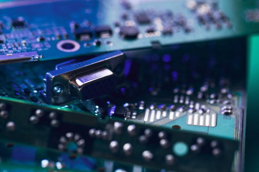
What is the Difference Between a Motherboard and a Circuit Board?
Two three-layer sheets are the basis of most motherboards. The copper layers are separated by a layer known as prepreg. This layer is then placed between two sheets copper foil. The epoxy resin is then cured on the prepreg, leaving two copper layers separated by the prepreg. The hardened three-layer sheet is then etched to reveal copper pathways, and the unneeded copper is dissolved.
Integrated circuits
A computer can have a number of integrated circuits that are interconnected and assembled on a motherboard. An integrated circuit can have a capacity of 1 Megabit, but it can also be up to 128 Megabits if it is assembled flat onto a motherboard. A motherboard that houses an image processor must contain one hundred and twenty eight elementary integrated circuits. This would create a large footprint. This would be impossible so an intermediate board is used.

An prior art motherboard 110 contains an integrated circuit 112 and a voltage regulator circuit (114), which supply the required voltage and current to other components. Because the motherboard is designed to support the integrated circuit 112, the voltage regulator must be modified to accommodate the new integrated circuit. Flexible motherboards may also be able to support different frequencies and voltage requirements. A programmable motherboard can accommodate these differences.
Printed circuit board
Here’s how a printed circuit boards differs from a motherboard. Printed circuit boards consist of fiberglass boards with copper trace that serve as a foundation to the actual motherboard. The PCB will display the circuit traces once it is assembled, much like a breadboard. A motherboard is used for many purposes. The main purpose of a motherboard is to connect all components together.
A PCB is the basis of most electronic components. It is the base of most electronics. It is commonly made from composite epoxy, fiberglass, or another material. Simple PCBs may only contain one layer, while more complicated hardware will have many layers. Comparing the two will reveal the difference between a motherboard or a PCB. Here’s a quick explanation of the differences.
Process of installing a PCB
The first step in the process of installing a PCB is to prep the PCB. Then, the layers are pressed together. The photoresist is then applied to the PCB’s outside layer. The next step is to image the photoresist on the outside layer. The outer layers are then plated with tin to protect copper on the outside layer, just as the interior layers.
The solder paste can be applied by hand to the board. It is similar to screen printing a shirt. To allow assemblers to apply paste only to the parts that will be installed, a thin stencil of stainless-steel is placed on top of the PCB. The board will be assembled and connected to its components. The board is now ready to be tested. It will go through a series of tests to ensure it is functional and high quality.